AI Test Vehicle for NIST
Project Overview Primary objective: The project goal for National Institute of Standard and Technology (NIST) is to provide measurement methods and metrics to study the interaction
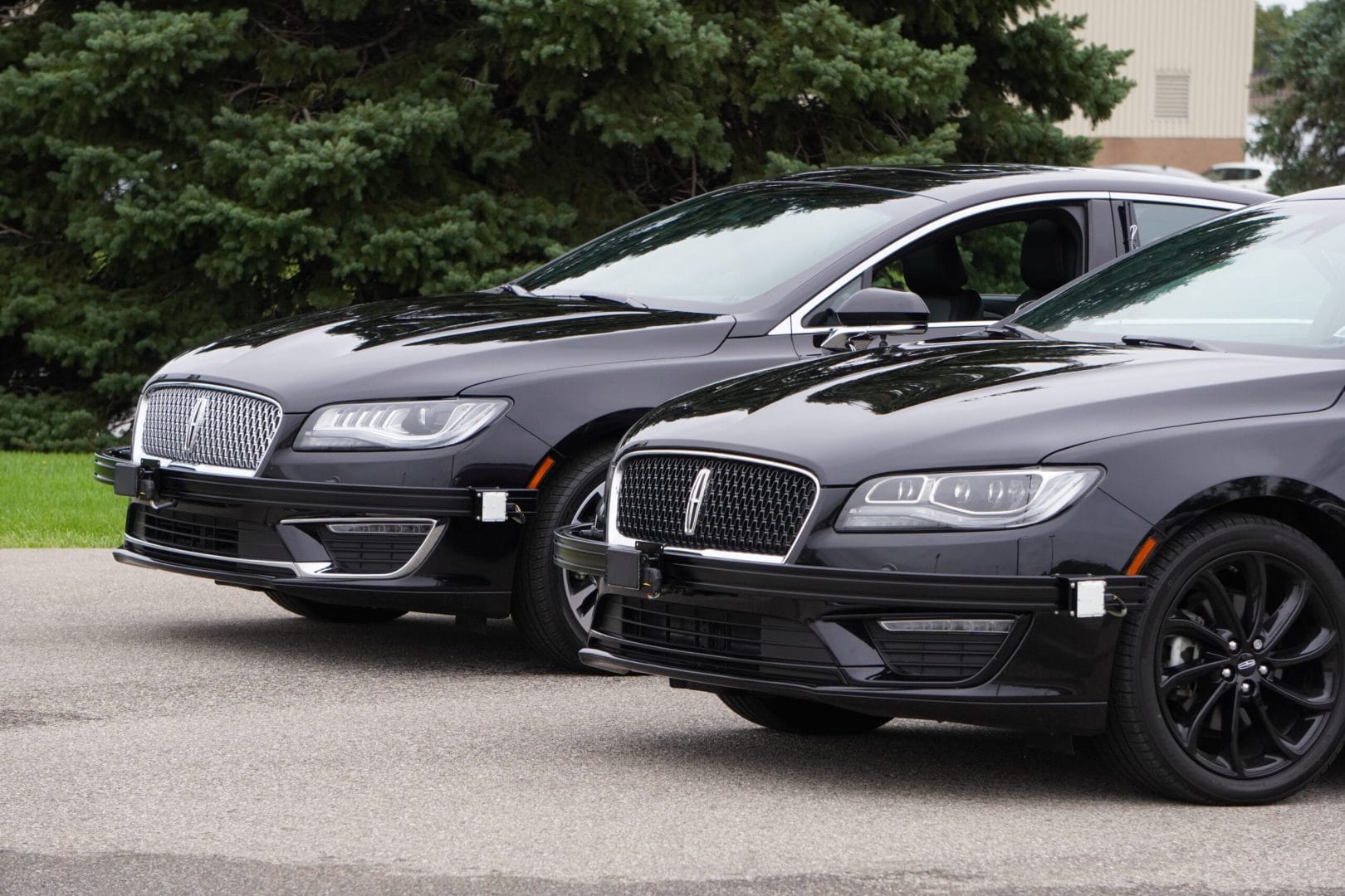
Modular Camera Suite Integration for AI Leader
Project Overview Primary objective: A leader in AI reached out to Dataspeed with the intention of creating a small fleet of autonomous capable customer demonstration
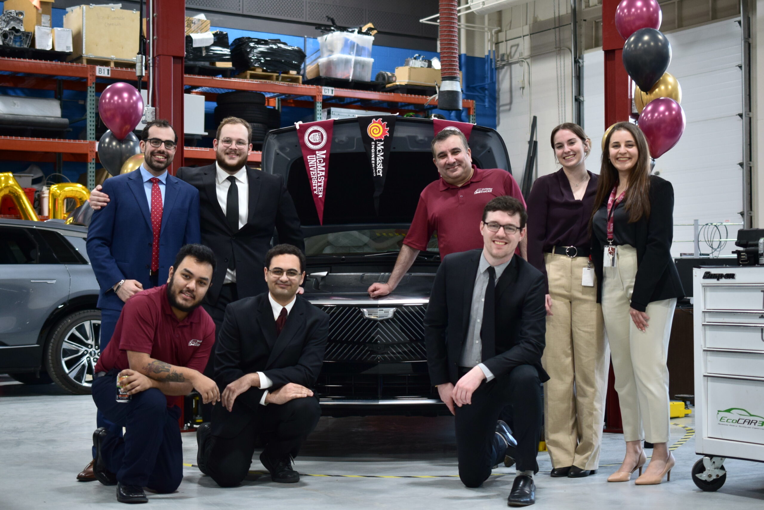
McMaster’s Innovative Use of Dataspeed iPDS in EcoCAR EV Challenge
Dataspeed is a Supporter level sponsor of the EcoCAR EV Challenge and has donated an intelligent Power Distribution System (iPDS) to each team. The McMaster
